Transformer Lab Manufacturer of a wide range of products which include Single Phase Transformer Back To Back Test, THREE PHASE TRANSFORMER 3 KVA and Open Test, Short Circuit & Polarity Test, Ratio Test On Single Phase Transformer. Load test on single phase transformer 5. O.C & S.C Test on a single phase transformer 6. Regulation of an alternator by EMF & MMF methods. V curves and inverted V curves of synchronous Motor 8. Load test on three phase squirrel cage Induction motor 9. Speed control of three phase slip ring Induction Motor 10.
Transcript
Description & Specification:Single Phase Transformer for Electrical Lab - 230V AC & has tappings at 100%, 60%, 33% etc for various experiments. This Model is an educational model suitable for demonstrating to students the complete know of the Basics, Study and Voltage conversion at various levels, Study of Efficiency & Maintenance of these.
Single phase transformers are used in power supplies and other equipment to convert AC voltages and currents from one value to another. Transformers are critical for providing electrical isolation which is necessary for the safe operation of many laboratory instruments and medical devices. If the input and output do not share a common terminal, then the transformer can transfer power with complete physical separation. This prevents electricity on the hazardous high-voltage side of a system from reaching circuits and people on the safe low-voltage side. Understanding the components within a transformer is important for transformer analysis and design. This video will demonstrate how to measure electrical parameters of transformer components by performing various tests.
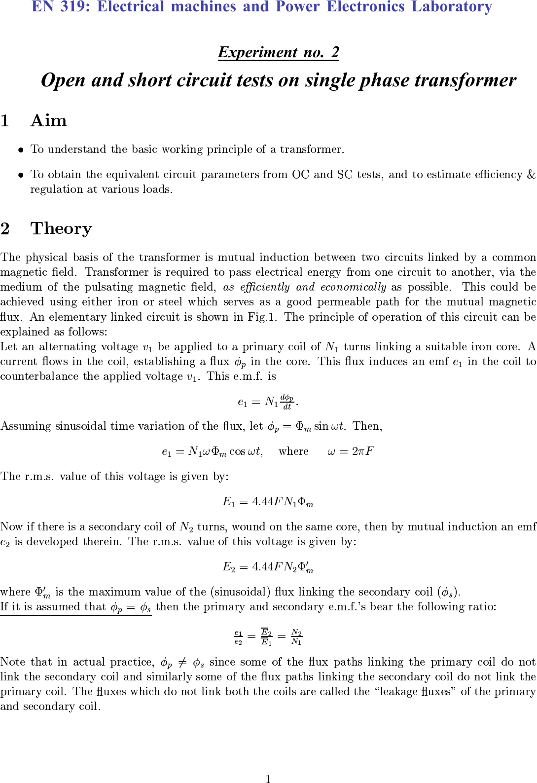
A transformer has a pair of input terminals connected to a primary winding or coil and a pair of output terminals connected to a secondary winding. A core consisting of steel, ferrite or even simply air magnetically couples the two windings. A voltage across one winding causes current to flow through it, creating a magnetic field. Magnetic flux, which is the amount of magnetic field passing through an area is then coupled through the core to the secondary winding where it induces a voltage. This principal is called mutual induction. Faraday's Law states that flux's rate of change times the number of windings is equal to the induced voltage. Also called the Electromotive Force or EMF. A DC voltage across the primary winding is constant therefore the resulting magnetic flux is also constant and the rate of change is zero. However an AC voltage produces a magnetic flux with a non-zero rate of change and consequently induces a voltage. In other words an AC voltage is required for the transformer to operate. The transformer turns ratio is the number of turns of wire on the primary winding divided by the number of turns on the secondary winding. The ratio of voltage across the primary to voltage across the secondary is equal to the turns ratio. Depending on the turns ratio a transformer can step up voltage, step down voltage or keep it the same. The ratio of current through the primary to current through the secondary is equal to the inverse of the turns ratio. For example if the primary coil has three turns and the secondary has 30 turns, the turns ratio is 0.1. Thus 120 volts on the primary of this transformer becomes 1200 volts on the secondary. 10 amps through the primary becomes 1 amp through the secondary. Finally if the secondary coil has a load of impedance Z2, the primary coil has an apparent or reflective load, Z2 prime. The value of this reflective load is the impedance on the secondary side multiplied by the square of the turns ratio. A transformer can be considered a pair of coupled inductors which ideally transfers energy without loss from one coil to the other. However a real transformer has leaked magnetic flux or leakage inductance which does not contribute to the transfer of energy between windings. Furthermore a real transformer experiences power dissipation and heating from winding resistances. Magnetic flux induced in the core is an additional source of heat due to core loss resistance. To avoid damage a specified maximum power input is used called the VA rating or the product of input voltage and the current which is power. Now that the basics of a transformer have been introduced, let's take a look at how to measure a transformer's electrical parameters.
The transformer used in this experiment is rated to tolerate a maximum of 115 volts on the primary winding and a maximum of 24 volts on the secondary winding. Furthermore, this transformer has a power rating of 100VA meaning that it can accept a maximum of 100 watts of power. This DC test measures the resistance of each winding for use in the equivalent circuit model of the transformer. First set the low-voltage DC power supply voltage output to zero volts and the current limit to 0.8 amps. Then turn the supply off. Connect the power supply output across the primary winding. Do not connect anything to the secondary winding. Turn on the DC power supply and increase the voltage gradually until the current limit is reached. Record the voltage and current readings from the display of the power supply. Calculate the resistance of the primary winding by dividing the voltage by the current. Set the power supply voltage back to zero volts and turn it off. Connect the power supply across the secondary winding leaving an open circuit on the primary winding. Set the current limit on the power supply to four amps. Then increase the voltage gradually until the current limit is reached. Record the voltage and current readings from the display of the power supply. Calculate the resistance of the secondary winding. Set the power supply voltage back to zero volts, turn it off and disconnect it from the transformer. Finally use a multi-meter to confirm the calculated resistances across the primary and secondary windings.
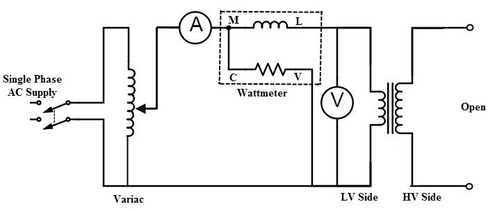
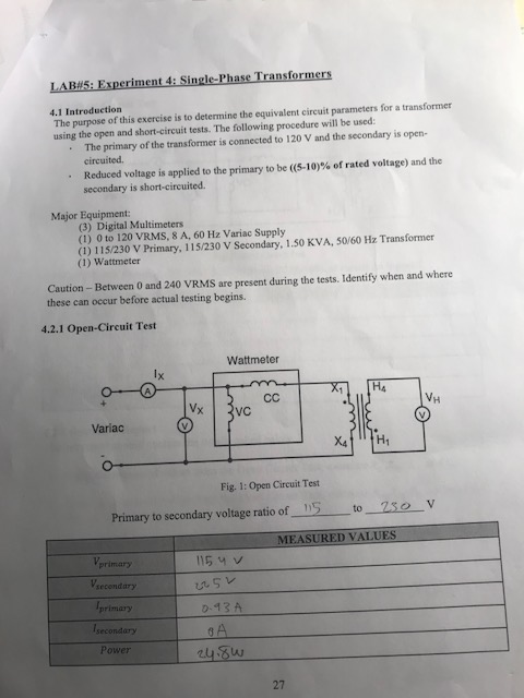
The open circuit test measures the mutual reactants or the opposition to a change in current from the core loss resistance. Core loss resistance is the equivalent circuit parameter for power dissipation and approximates power losses in the core of the transformer. With the three-phase power source off and the Variac set to zero percent, assemble the circuit as shown. Then use a digital power meter to measure open-circuit current and voltage on the primary side. Turn on the three-phase power source and slowly adjust the Variac's control knob to increase voltage until the digital power meter reads 24 volts. Record the open-circuit voltage, open-circuit current, open-circuit real power and power factor. Use these values to calculate equivalent circuit parameters for the transformer. The core loss resistance, RC is calculated from the open-circuit voltage and open-circuit power. The mutual reactance XM is calculated similarly using open circuit voltage, power and current.
The short circuit test measures the leakage reactants and can also determine the wire resistance of both windings. First calculate the rated input current of the transformer by dividing the VA rating by the voltage rating for the input side. With the power source off, and Variac at zero percent output assemble the circuit as shown. This time use the digital power meter to measure short circuit current and voltage. Turn on the three-phase power source and slowly adjust the Variac to increase voltage until the current reading on the digital power meter reaches the rated input current. Record the short circuit voltage and current as well as the short circuit real power and the power factor. The leakage reactants is the sum of the primary side reactants and the reflected secondary side reactants which are assumed to be equal. Calculate the leakage reactants with the measurements from the short circuit test. Finally calculate the total wire resistance of both windings as the sum of the resistance of the primary winding and the reflected resistance of the secondary side winding.
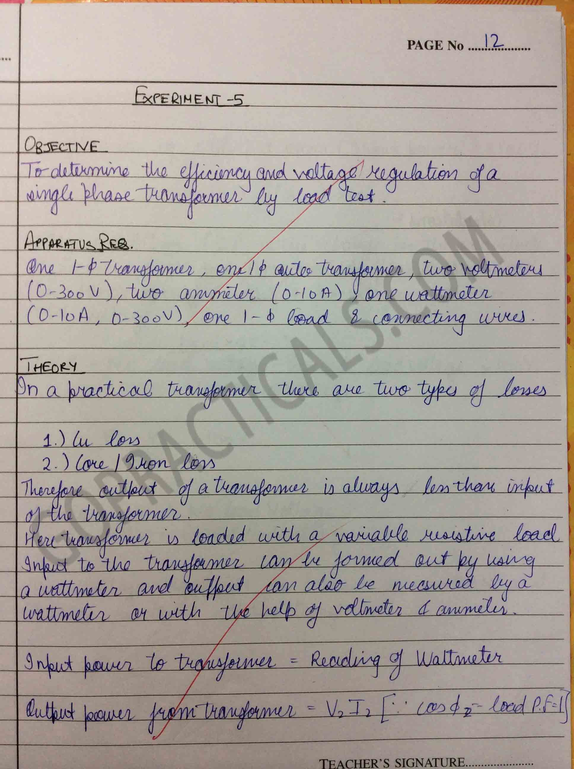
Transformers are very useful electrical devices which have applications in the area of power conversion and electrical isolation for safety. The load test measures the ratio of voltage across the primary to voltage across the secondary as well as the ratio of current through the primary to current through the secondary. The circuit was assembled with a 100 Ohm resistor connected to the secondary side and the current and voltage measured on both sides. With the primary side at 115 volts, the voltage, current, real power and power factor were measured on both sides. The ratio of the primary voltage to secondary voltage should ideally equal the turns ratio. A study of the olfactory sensory neurons of mice used ultraviolet light from a xenon flash tube to dissociate certain compounds. The circuitry to drive a flash tube required high voltages generated with a step-up transformer. As with all high-voltage equipment, safe design uses transformers for electrical isolation to prevent accidental short circuits between components with dangerous voltages and other electronics in the circuit.
You've just watched Jove's introduction to single-phase transformers. You should now understand how a transformer works as well as how to measure its equivalent circuit parameters. Thanks for watching!
Objective:
- To study the voltage and current ratios of a transformer.
- To learn about transformer-exciting currents, volt-ampere capacity and short-circuit currents.
- A Single Phase Transformer
- Power Supply
- AC Ammeter
- AC Voltmeter
- Wires
o1. Examine the construction of the Single-Phase Transformer paying particular attention to the transformer, connection terminals and the wiring.
- The transformer core is made up of thin sheets (lamentations) of steel. Identify it.
- Note that the transformer windings are brought out to terminals mounted on the transformer coil.
- Note that these windings are then wired to the connection terminals mounted on the module face.
- List the rated voltage for each of the three windings:
- List the rated voltage between the following connection terminals:
- List the rated current for each of the following connections:
o7. a. Connect the circuit shown in Figure-2. Notice that current meter I2 short-circuits winding
Single Phase Transformer Experiment Report
- Return the voltage to zero and turn off the power supply.
- Calculate the current ratio:
- For a transformer the turn and current ratio are inversely equal. So theoretically the voltage and current ratio is not equal. Because-
| Figure - 3 |
Single Phase Transformer Experiment Theory
Single Phase Transformer Diagram
Single Phase Transformer Lab
E1 | I1 | E2 |
50 | 45 | |
0 | ||
150 | 145 | |
0 | ||
250 | 240 | |
0.2 | ||
350 | 340 | |
0.5 |
Comments are closed.